1. Introduction
For many years, I have relied on a single Western Digital My Cloud device equipped with a 2TB hard drive as my primary backup solution for my home lab. While this setup has served its purpose to some extent, it presents several significant limitations that have increasingly become difficult to ignore. Chief among these issues is the complete lack of redundancy, meaning that if the drive fails, all data will be lost. Additionally, Western Digital’s proprietary software limits flexibility and prevents me from running additional software and monitoring. Over time, it has become clear that this is not a sustainable solution.
Recognizing the need for a more robust and adaptable backup solution, I began researching alternative approaches and evaluating a range of options. During this process, I came across an impressive project by Michael Klements, which uses a Raspberry Pi with 3D-printed components and various off-the-shelf hardware to build a custom 4-bay NAS. This unlocks customization, scalability, and control that far exceeds the limitations of the My Cloud system. You can read the full original build here: Building a 4-Bay 3.5″ NAS. This design addressed nearly all of my requirements, providing the redundancy, flexibility, and expandability I was looking for—though there are some design tweaks I wanted to make.
2. Changes from the original
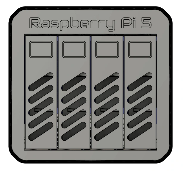
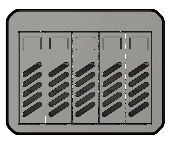
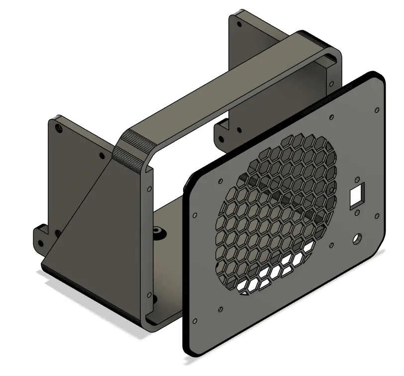
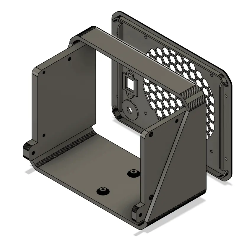
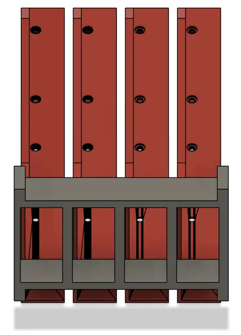
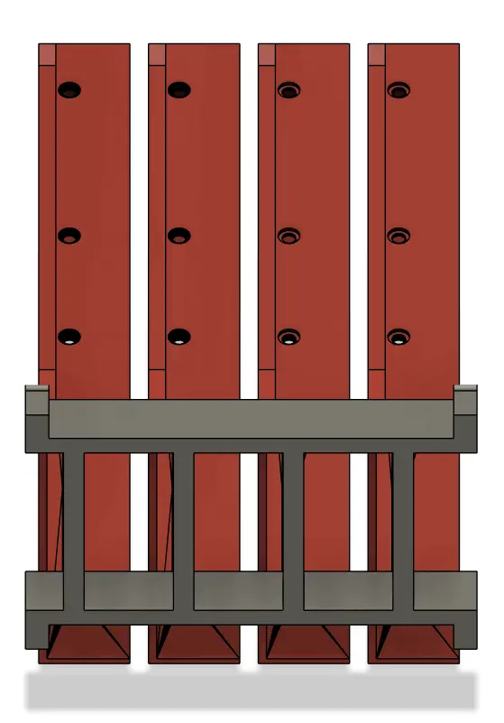
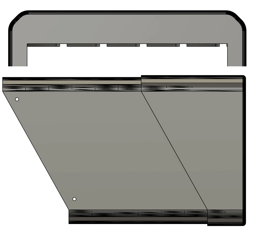
The project uses the Radxa Penta SATA HAT with five SATA ports (four full ports + one e-SATA), the original enclosure only supports four drives from the four full ports. I widened the chassis and added a fifth bay to allow all five ports to be used.
Adding the fifth drive requires using the eSATA port, which would have meant an external cable poking out the rear. To avoid this, I rotated the Raspberry Pi inside the enclosure, at the cost of losing direct access to the Pi's USB and ethernet ports.
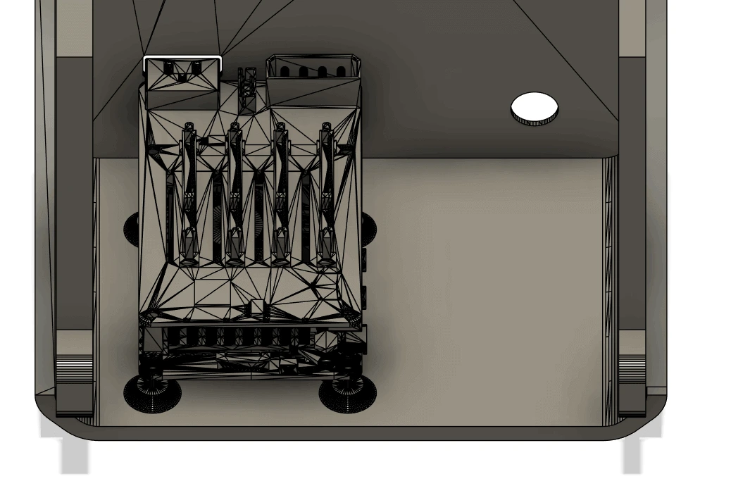
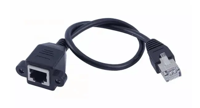
Since it being a NAS, the only ports I really need are power and ethernet, so I opted for using a panel-mounted Cat5e extension. This also allows me to add a 2.5Gbps USB ethernet adapter inside the chassis, should I ever need it.
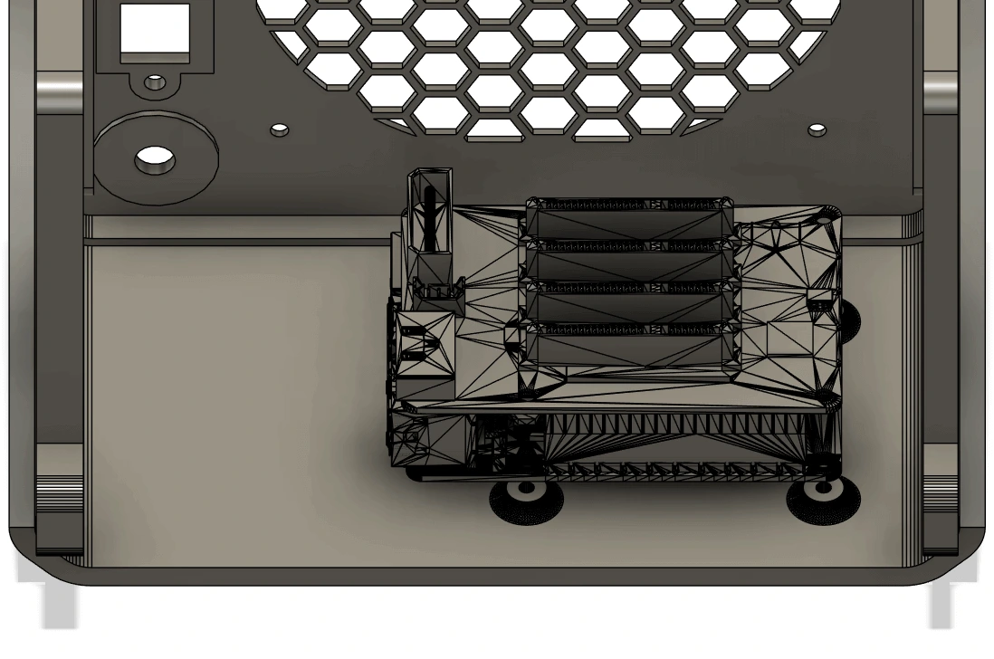
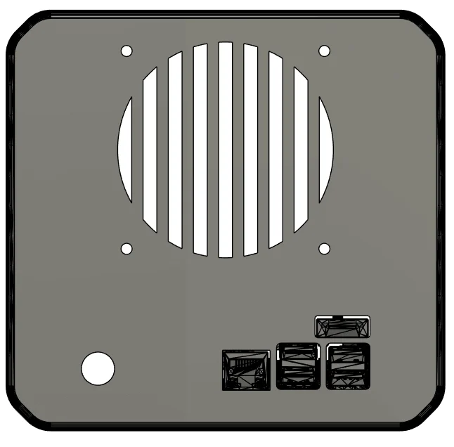
The larger chassis made it possible to upgrade from a 80mm fan to a full 120mm fan, reducing noise while improving airflow. Not to mention that the standard for PC fans is 120mm, therefore, finding a high-quality 120mm one is going to be much easier than finding a 80mm one. I opted to go for a hexagonal pattern instead of the original vertical bars.
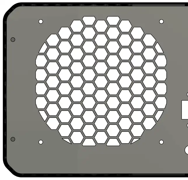
The larger fan also meant a new fan cover was needed, I simply copied the hexagonal mesh and added the relevant holes for the brass inserts.
Image TBC
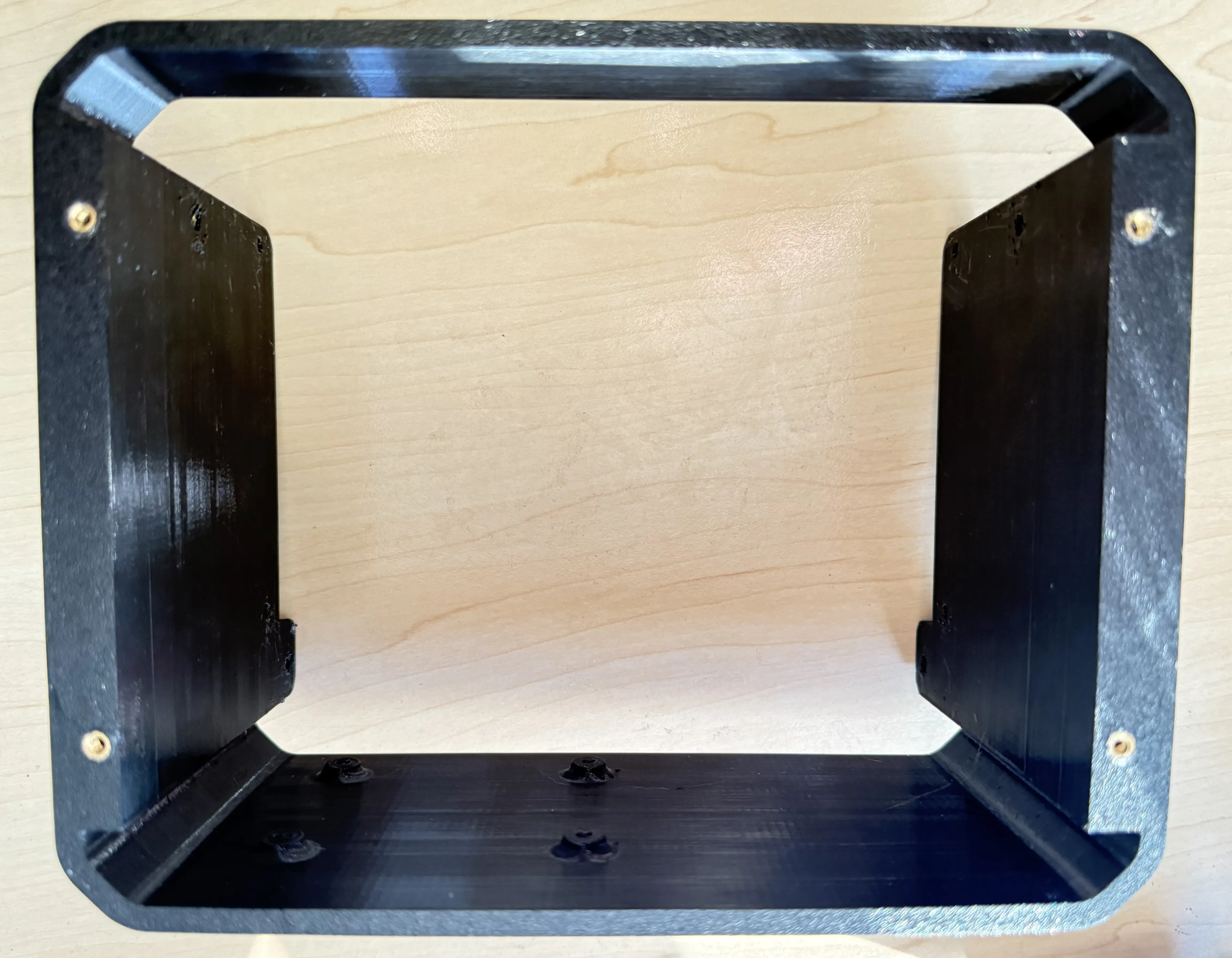
I also decided to redesign the rear panel and make it a removable part. This avoids reprinting the entire rear of the chassis if I want to add more ports or if I simply want to access the internals. It adds a few more brass inserts and screws but greatly improves flexibility.
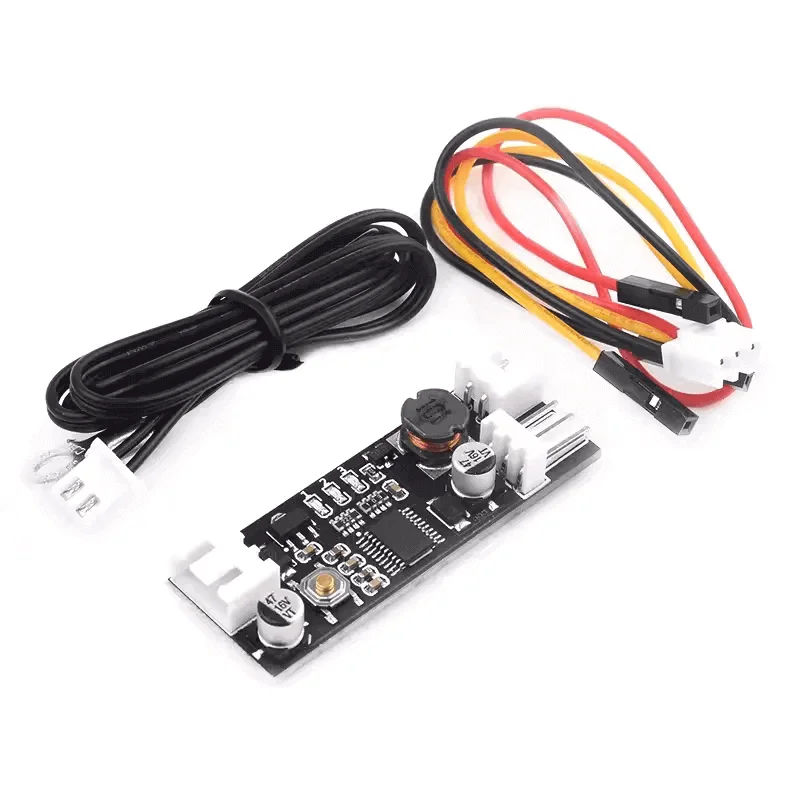
I also had a concern about the original build, which connected the fan directly to the 12V on the Molex connector. This would mean the fan constantly runs at full speed, which will be noisy, as well as reduce the lifespan of the fan. I wanted to use the hard drive temperatures to control the fan from the Pi, after some research, I couldn't find a quick, clean way to achieve this. So I ordered a PWM controller with a temperature probe to control the fan speed instead.
After making all the modifications, I realized the fan is blocking the 5.5mm DC port. To avoid making any more changes to the design, I simply opted to feed power in via the Molex connector instead. Since I am still going to be using the DC extension cable as the original design, it doesn't really add any complexity.
Photos will be added as soon as I built the first unit, it was hard getting a good picture from Fusion.
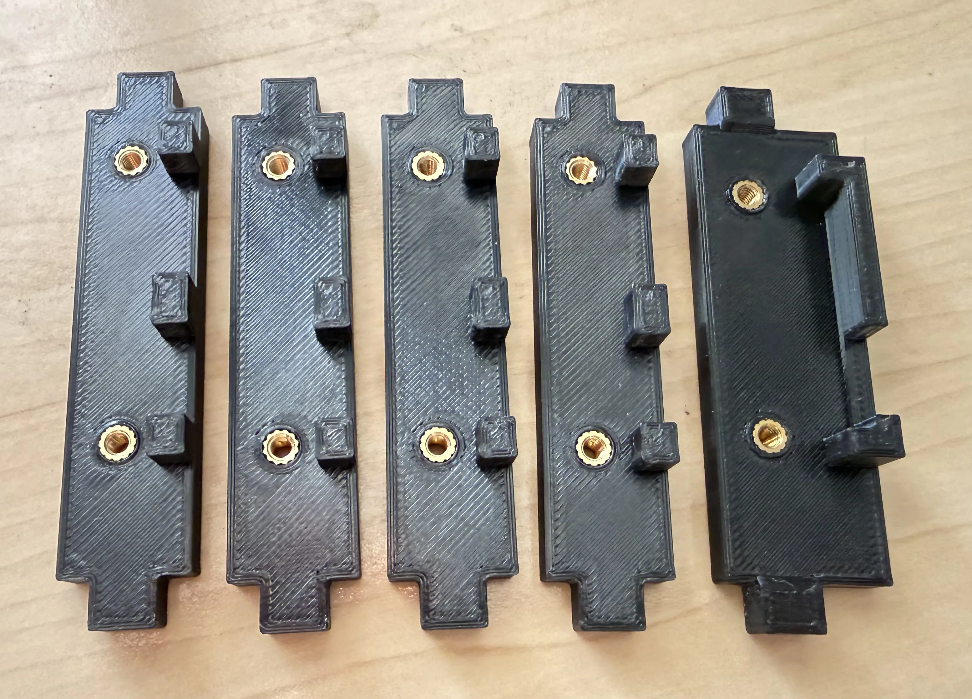
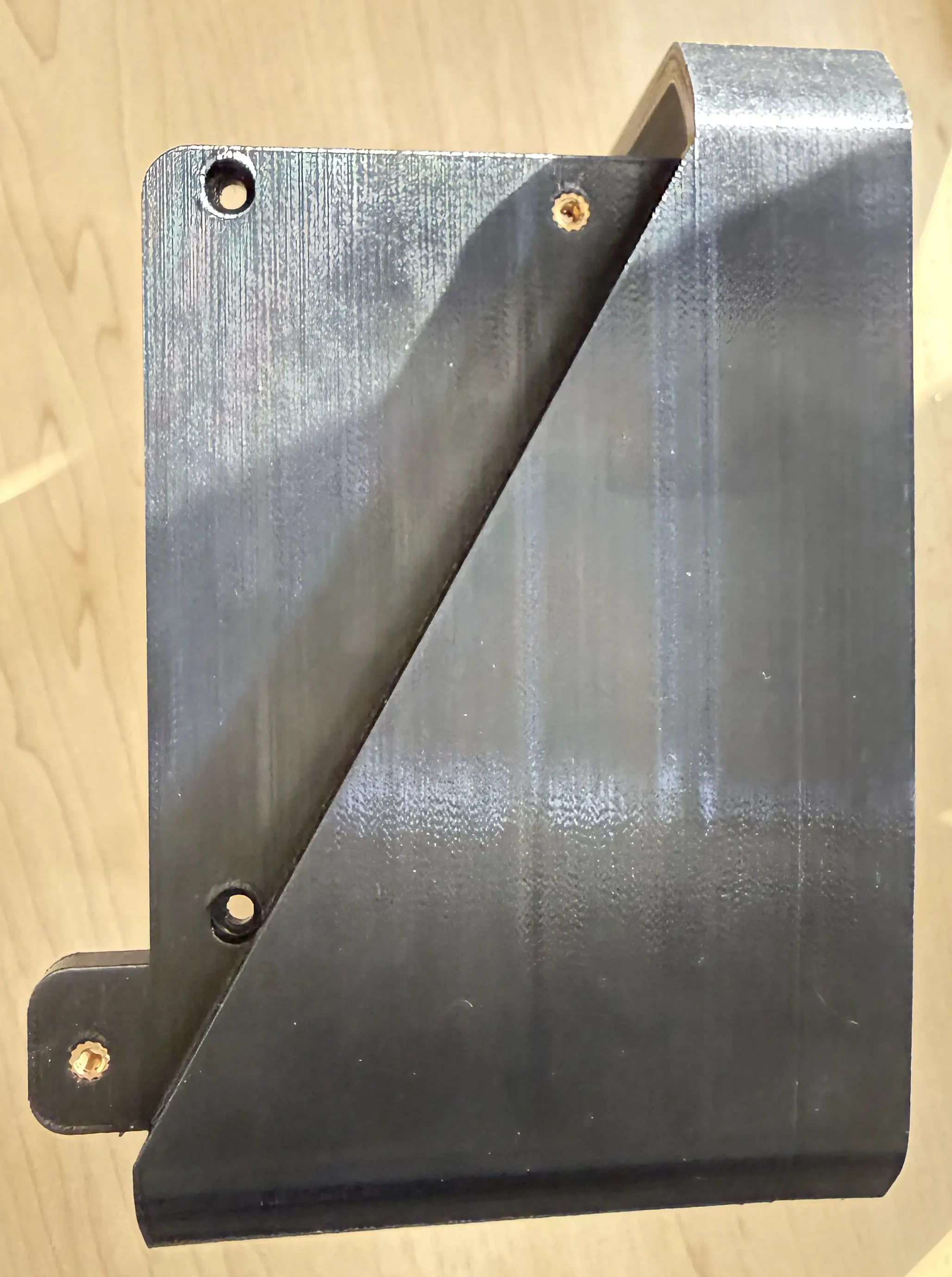
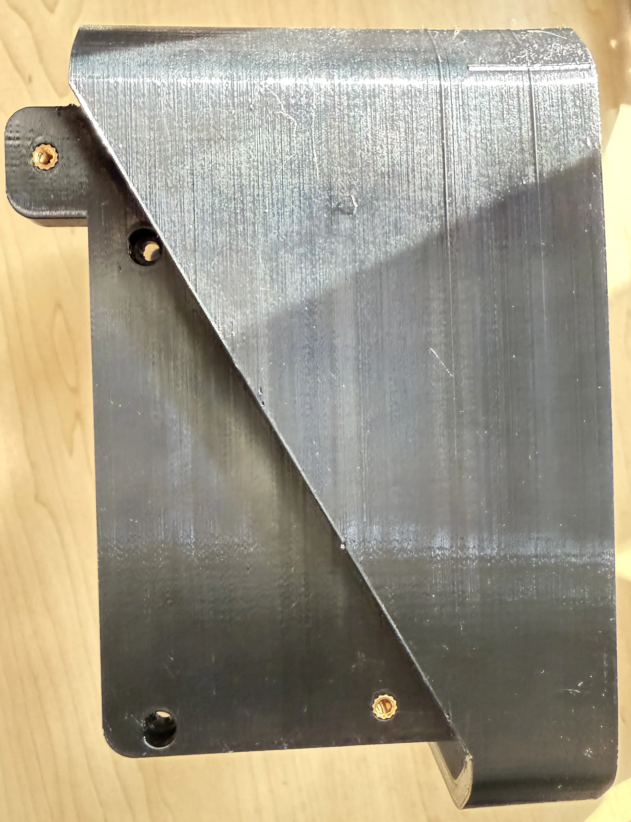
I also noticed that the original bracket that holds the SATA connectors sat directly in line with the opening between the hard drives; this will restrict airflow when using thicker drives. The brackets were moved to the other side of the sata connector, directly behind the hard drive, to create a straight path for better airflow.
On the original design, the brass inserts and screws on the original had to be assembled in a specific order with long tools, something I wasn't particularly fond of. I made the SATA bracket modular so that everything is restricted in place when screwed into the chassis, I also added pins behind the SATA connectors to help with orientation during assembly. During the initial test fit, I didn't like the fan controller's temperature probe was just hanging freely, so I added a brass insert to the top of the bracket to srew it in to.
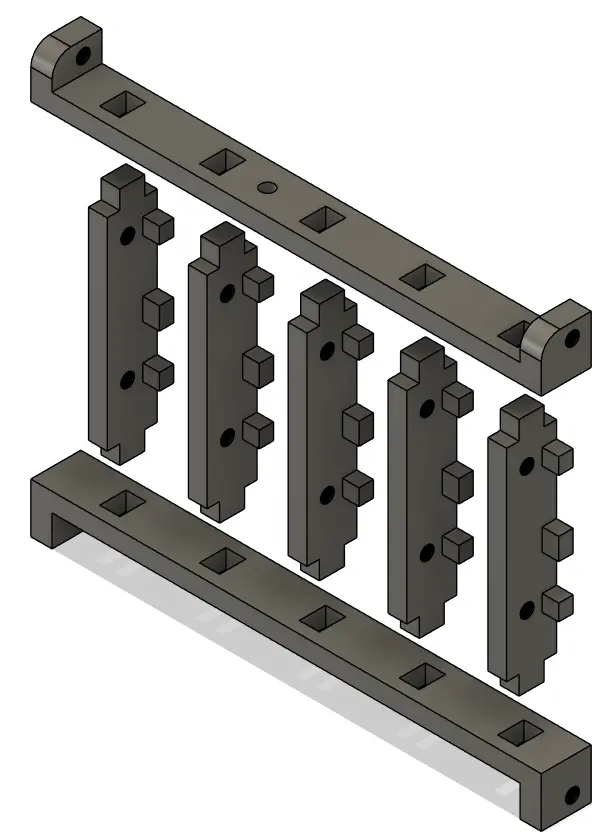
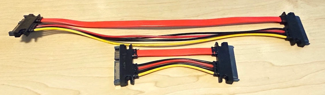
I used 10cm SATA cables instead of 30cm cables to reduce clutter and improve internal airflow.
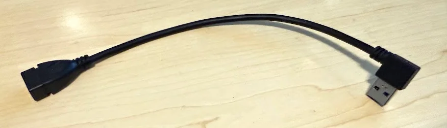
The Pi boots from one of the official Raspberry USB drives and is connected via a short USB extension cable for easy accessibility.
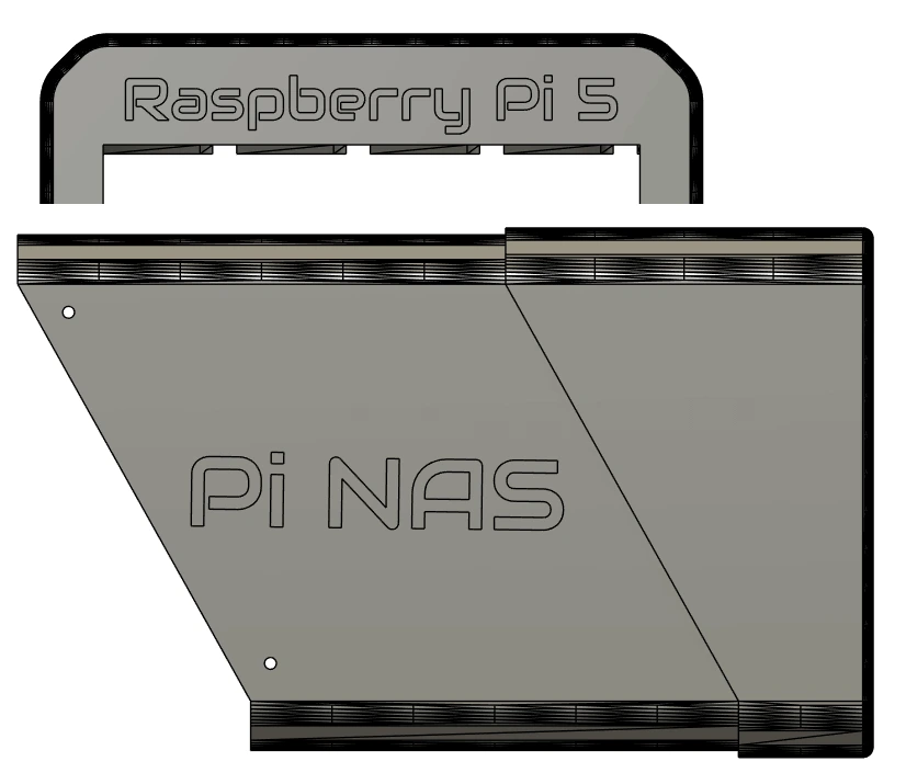
For a cleaner look, I removed the front “Raspberry Pi 5” and side “Pi NAS” branding.
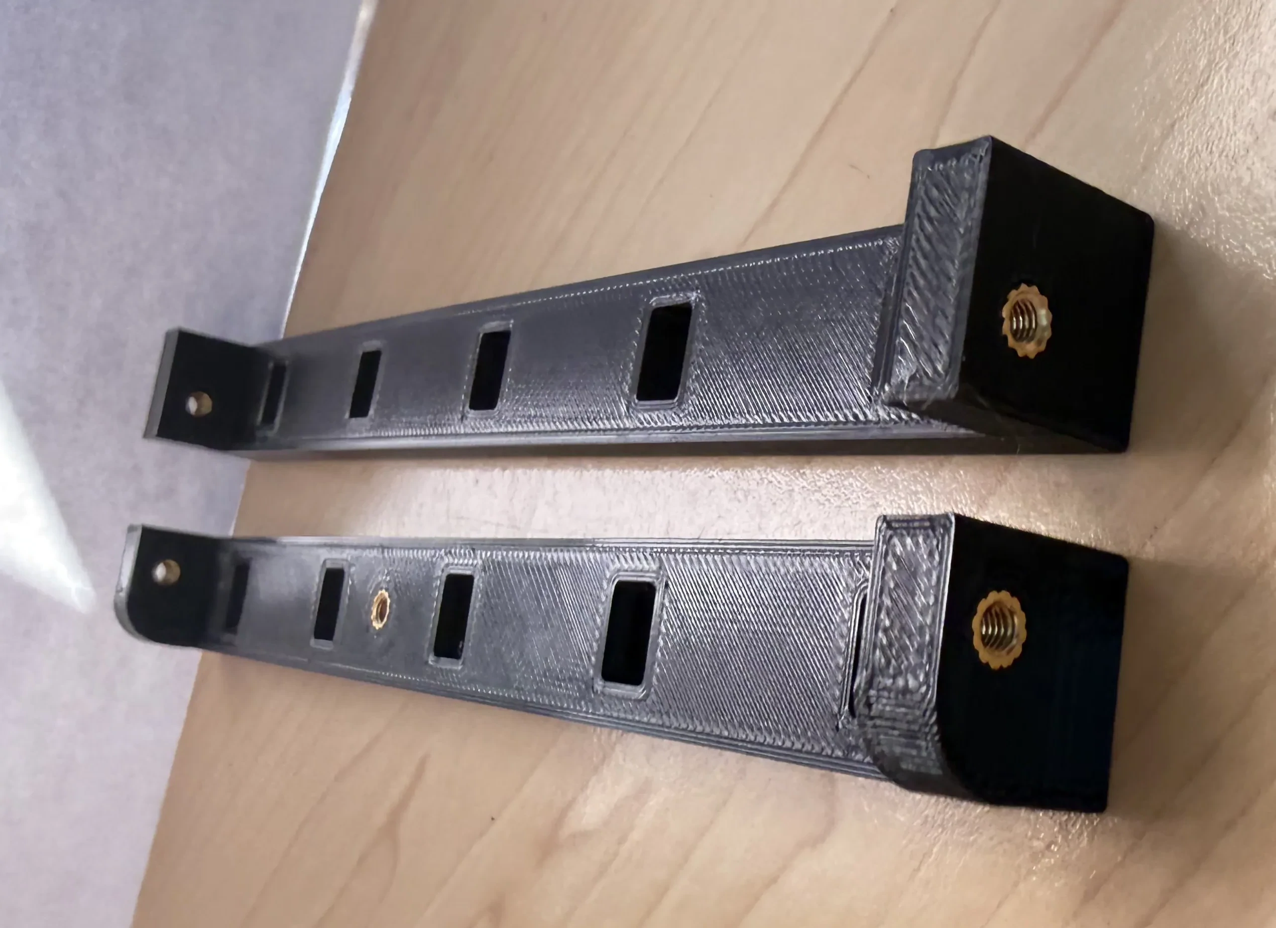
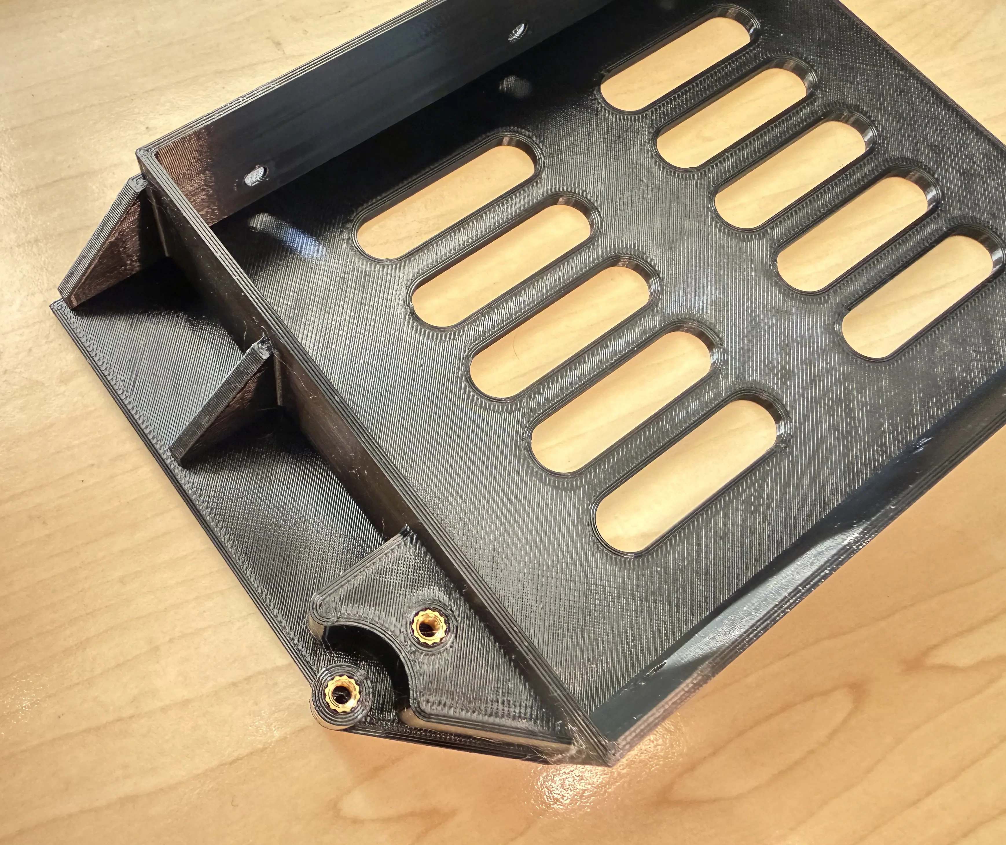
During test fitting, I discovered that there is a significant amount of flex in the drive tray when pulling on the handle to remove a drive. To combat this, I added a secondary brass insert and altered the washer to act as a bridge on the 'top' of the handle.
Overall, the NAS was upgraded to five bays with several quality-of-life improvements and minimal additional hardware. The biggest drawback is slightly higher filament usage, which is about 1.25kg, meaning multiple spools are needed whereas the original required less than 1kg. There are some optimizations that could reduce it to a single spool again, but I am happy with the current state.
3. Printed parts
The printed parts can be found on Thingiverse.
These values might not be exact, it is what the slicer provided for the various files to be printed in PETG using the '0.2mm structural' setting on my Prusa Core One with high-flow 0.4mm nozzle.
| Part | Filament | Print time |
|---|---|---|
| Sata holder assembly | 50.6g | 2h 40m |
| Drive tray set (each) x5 | 77g | 3h 07m |
| Rear body | 226.6g | 10h 27m |
| Front body | 690g | 1d 7h 36m |
| Rear panel | 55g | 2h 15m |
| Fan cover | 27g | 1h 51m |
4. What You Need
- Raspberry Pi 5 - I chose the 16Gb model
- Heatsink for the Pi - I recommend the Argon THRML 30mm, I could only get the original Raspberry one locally
- Radxa Penta SATA HAT (Kit)
- 4/5x SATA extensions (See build guide for more info)
- Boot drive (USB/SD) - I chose the Raspberry Pi Official USB drive
- Data drives - I went with a single Seagate IronWolf NAS to start
- 12V Power supply - Wattage depends on your drives - I went with 96W (8A)
- 5.5x2.5mm panel mount DC jack (XXmm drill size) pre-wired or buy wire
- 120mm slim fan (Specifically a PWM one)
- PWM fan controller
- Molex connector (I just bought a cheap splitter)
- M3x6x5 Brass inserts (37 PCS)
- M3x8mm Button Head Screws (22 PCS)
- M3x20mm Button Head Screws (4 PCS)
- Hard Drive Screws (20 PCS)
- M2.5x6mm Screws (4 PCS)
- Panel mount Cat5e extender (10-30cm) + screws
- CA Glue (super glue) - See fan controller section below
- 2.5Gbps USB ethernet adapter (OPTIONAL)
- 1.25kg PETG + Access to a 3D printer
- Soldering iron for soldering and inserting the brass inserts
- Insulation tape or heat shrink to cover solder joints
- A lot of patience waiting for the 3D prints to complete
5. Install the Operating system
While waiting for the printer to finish making all the parts, it is a good time to flash the operating system to the boot drive so it is ready for assembly.
The placement of the Pi in the case also doesn't allow for the SD card to be removed once the Pi is screwed into place. I am using a 128Gb official Raspbrry Pi drive for this.
Install the correct Raspberry Pi OS Image, follow the OpenMediaVault guide until you get to 'The First Boot', we'll continue later once we've built the NAS: OMV 7 Raspberry Pi Install
Since we won't be powering the Pi via USB-C, it will complain about power and say it needs a 5V 5A power supply. To make it boot, remove and re-insert the USB drive into
your PC, and on the bootfs drive edit config.txt and right at the bottom add the following line:
usb_max_current_enable=1
IF YOU SKIP THIS STEP, THE PI WILL NOT BOOT!!
Save the file and remove the USB drive, it is now ready to be used in the Pi.
6. Brass inserts
After the prints came off the printer, the first thing to do was to install the brass inserts. There are multiple guides on how to do this with whatever tools you have available.
- (10) Two in each SATA holder x5
- (5) Top and Bottom SATA holders
- (8) Four for the rear body back lid and two on each side
- (10) Two in each drive tray x5
- (4) Fan cover

Image TBC
7. Preparing the Pi
The stock Raspberry Pi cooler is designed in such a way that interferes with the Radxa HAT's power connector. You can either use a different cooler, like the Argon THRML 30mm or take the destructive approach of either desoldering the power connector from the HAT or cutting some pins off the heatsink, or. I opted for the latter.
Image TBC
After any necessary modifications have been made, mount the cooler to the Pi, it should just click in place. The fan connector has a cover on it from the factory that needs to be removed to connect the fan.
Image TBC
Next, mount the HAT using the provided hardware; ensuring that the 2.5mm threaded holes are at the bottom. I recommend plugging in the PCIe cable before plugging in the HAT, it's much easier than trying to fiddle with it afterwards.
Image TBC
8. Rear body assembly
Grab the rear body printed part and screw the Pi assembly to it using the M2.5 screws.
Image TBC
Next we'll mount the SATA cables.
Start with the e-SATA port. I highly recommend marking the side that plugs into the HAT somehow to know which side is up.
Since it's cable is the longest, it goes on the first (left) slot and can be mounted in 3 ways:
1. Using a 10cm extension and M3x8 screws (Same bracket as the other ports)
2. Drilling 2 holes in the e-SATA connector and using the e-SATA specific bracket (Use the bracket to mark the homes and drill 3.5mm holes)
- This will require longer M3 screws than the standard 8mm ones - 10mm or longer works.
3. Using a male to female connector (I have not tested this, but it should work)
Image TBC
The middle 3 slots are easy - use 10cm SATA extensions and M3x8 screws (You can use longer ones, I prefer the 10cm to keep it clean)
Image TBC
Slot 5 (right) also has some options as well:
1. You can use a 15cm or 30cm SATA extension, which means no modifications
2. You can extend the power of a 10cm one since it only needs an extra 1-2cm to reach; the data connection is long enough I went with this option.
Both options use M3x8 screws
Mounting the SATA connectors to the body I found the easiest is to screw the bottom holder to the body, then insert the upright sections and fix them in place with the top holder. NOTE: These have a specific orientation to ensure the SATA ports align with the drives. The top holder has a rounded corner to match the body, so ensure the holes line up for the bottom one. The brass inserts are closer to the rear of the holder.
Image TBC
Now plug the SATA cables in to the HAT, I put slot 2 in the front-most port on the HAT, then slots 3 and 4; finally, slot 5 is the longer (or modified) cable into the rear-most port.
Image TBC
The temperature probe is mounted in the top SATA holder. Screw it to the top of the holder using an M3x8 screw and route the cable as shown.
Image TBC
9. Fan controller configuration
Deciphering the instructions on the AliExpress page for the fan controller was a bit of a challenge, but I believe I managed to get it working.
Don't take my word that these settings are correct know if these settings are correct, but here is what I did:
- Hold the button while plugging in the power until lights flash - The device is in 'mode' configuration.
- Single-press until light 2 is solidly on - This makes the fan turn off completely if the temperature is 5C lower than the fan start temperature.
- Hold until there is a change in the lights - This exits 'mode' configuration.
- The device is now in the 'running' state.
- Double-press until light 1 is on and 2 is flashing - This lets the fan start spinning at a lower rpm when the temperature threshold is reached.
- Hold until you see slow flashing.
- Double-press until light 1 is flashing slowly - This sets the fan start temperature to 30C.
- Hold until you see fast flashing.
- Double-press until light 1 is flashing fast - This sets the fan curve to ramp up/down at 5C intervals.
- Test by warming probe by simply holding it in your hand and cooling it down by leaving it in front of the fan. The fan should start and stop when it reaches thresholds.
NOTE: The device exits configuration mode if no input was given for a few seconds and returns to the 'running' state (Step 4).
10. Rear panel assembly
The barrel connectors I bought came with a short wire already attached, so I just screwed it into place.
I cut off the one connector from my MOLEX extension removed the 5V and one GND pin, since 5V is unused in the setup, the pins align much easier when plugging it in.
I also cut off the signal wire from the fan controller's power connector, since it won't be used.
I then soldered bother the fan controller's power and MOLEX connector to the barrel jack's leads, using heat shrink to keep things tidy. You can use electrical tape here as well.
NOTE: Once this is soldered, you can't remove it in case you print a different back panel without desoldering the connections. This isn't a problem for me, but something to keep in mind if you are following this build.
Image TBC
The ethernet extension I bought was 30cm, I shortened it to 10cm to keep things neat. You can order a 10cm one, or just coil up a 30cm onr.
It also came with 2 screws, but they didn't match the other ones I am using, so purely for aesthetic reasons, I replaced them with 2 that match.
Image TBC
Next the fan, use a slim (15mm) fan, I used the Arctic P12 slim. Pass the screws through the rear cover and the fan, and screw it into the fan cover.
Image TBC
The fan has four pins, but the controller I have only has three. The four pin connector couldn't plug into the controller due to the layout of the PCB, so I cut off one of the leads from the fan and soldered on to the controller. I also had to move over one pin, so that the three pins are next to each other, instead of having a gap in the middle to make the fan work with the controller.
Image TBC
I printed and glued in a separate mount for the fan controller since there are many variants and the mount I used might not fit your controller. The fan controller slides into place and everything just plugs in.
Image TBC
11. Front body
Screw on the front body
12. Hard drive assembly (x5)
To install the handle, slide it over the pin and screw it into place with the spacer bracket and two screws. This was updated from the single washer in the original design, the entire plate flexed a lot, it felt like something was going to break when I tried to pull a drive out of the NAS.
To mount a hard drive, screw it in using four screws. I am only using 3.5" drives in this design, if you want to use 2.5" drives, you will have to use a 2.5" to 3.5" adapter. There are many options to choose from online to either buy or 3D print yourself, just make sure that the SATA connector ends up being in the same location as a 3.5" drive.
13. What's next
Setting up the software.